
Overview
The OpenEdge Configuration dialog box provides a centralized interface to manage network settings, WAN/LAN/Wi-Fi interfaces, system updates, and device transfers. This unified view simplifies editing, adding, and monitoring interfaces and configurations for each network device in your system. It enables network administrators and operators to configure devices remotely with full visibility and control.
-
Click the
-20250730-194535%20(1)-20250811-125209.png?cb=391d028dd86f9d31b32b39905ae08688)
-
The Configurations dialog box contains the following options in its left menu bar - Interfaces, WAN, LAN, Wi-Fi, System and Association. These options can be used to create, copy and modify various configurations for the selected device.
Interfaces
-
The Interfaces option is selected by default. The system displays details of all pre-configured interfaces to the user. The user can view and manage all physical and virtual interfaces.
-20250811-142035.png?cb=4fc0eafb3911965677cb522c92d20ef3)
-
The user can view and update the configuration of the Interfaces present on the System.
-
There is a flexibility that any ethernet interface on the System (applicable for all products) can be configured as either WAN interface, LAN interface or for VSAT management. Along with this flexibility, VLANs can be configured on the interfaces and the same can be configured as WAN sub-interface or as LAN access port.
Interfaces are physically labelled on the hardware device as WAN or LAN, but can be configured as either a WAN or LAN port depending on the needed function.
-
The user can press on the Refresh button to refresh the page and get the latest data. By default, this screen refreshes every 30 seconds.
-
There are three types of Interfaces i.e., WAN, LAN and WiFi.
The Interfaces table shows the following information:
-
Enable/Disable Toggle - Click the Enable/Disable Toggle button to enable or disable this network interface.
-
Name - This shows the Alias of the network interface that is available on the device.
-
The connection status is denoted by following convention:
-
Green - Connected (link up)
-
Red - Disconnected (link down).
-
-
-
Physical Interface - Shows the actual hardware port or wireless interface on the device.
-
Type – The logical role of the interface, such as LAN, WAN, or Wi-Fi LAN.
-
Link Type – Defines the operational mode of the interface link, such as LAN Trunk (carrying multiple VLANs) or Ethernet (single network link).
-
Assignment – Lists the networks or profiles currently mapped to that interface.
-
Actions - Click the

-
Use the filter buttons

-
Click the
Add Interface
-
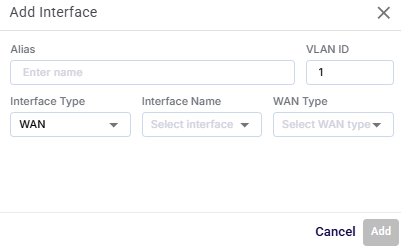
Click the Add Interface button to add new WAN or Wi-Fi interfaces and assign configuration details. LAN interfaces are system default and cannot be newly created.
-
In the Alias field, enter a name for the interface.
-
In the VLAN ID field, enter the VLAN tag associated with the interface (numeric).
-
In the Interface Type field, select between WAN, or Wi-Fi.
-
In the Interface Name field, select from the list of available physical or logical ports.
-
If 'WAN' is selected as Interface Type, user can also configure the WAN Type, which is one of:
-
Cell
-
Ethernet
-
L-Band
-
OneWeb
-
Starlink
-
Starlink Residential
-
VSAT
-
VSAT-HighSpeed
-
VSAT-Ka
-
VSAT-Ku
-
VSAT-Unlimited
-
VSAT-VOIP
If Interface Type is ‘LAN’, user can also configure the LAN Type, which is one of:
-
LAN Trunk
-
LAN Access.
-
-
If the interface type is set to Wi-Fi, the below additional Wi-Fi specific configuration options are shown.
-
Enter the SSID.
-
Enter the Alias.
-
Interface Type is selected as WIFI.
-
Select the Mode - WAN WI-FI or Access Point.
-
Select the WI-FI Band - WIFI 2.4 or WIFI 5.
-
Select the Security - WPA2/WPA3 or Open.
-
If the Security is selected as WPA2/WPA3, set a password in the Password field.
-
-
-
Validation occurs for duplicate alias names or reserved VLAN IDs.
-
The 'Add' button becomes active once all mandatory fields are filled.
-
Click the Add button to create the interface.
-
Click the Cancel button to discard the input and close the dialog.
SD-WAN
-
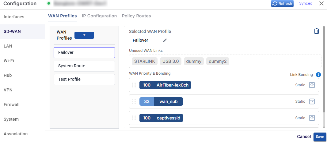
Select the SD-WAN option from the side menu bar to open the WAN tab. This tab enables the user to create and manage WAN Profiles with link bonding and priority.
WAN Profiles
-
The WAN Profiles tab is selected by default.
-
While the OpenEdge System is installed on the site, a default WAN Profile is created with the priority of the enabled WANs configured in this WAN Profile and assigned to the default Access Network. However, user can create multiple WAN profiles of their choice.
-
It is possible to configure any individual VLAN, subnet or even device in a way that the Internet traffic that entity is carried by more than one WAN link, based on conditions. This feature is called bonding, and the set of WAN links is called the ‘bonded set’. Within WAN profiles, if any priority levels contain more than one WAN link, then those links in that priority level form a bonded set. It should be noted that, should any one link in a bonded set fail, while new TCP or UDP sessions would be assigned to one of the surviving links of the bonded set, any sessions currently using that failed link will be lost.
-
The user can press on the Refresh button to refresh the page and get the latest data. By default, this screen refreshes every 30 seconds.
Initially, the Default WAN profile is available. User can create multiple profiles. Once, the profiles are configured, the profiles become available under the WAN Profiles section.
-
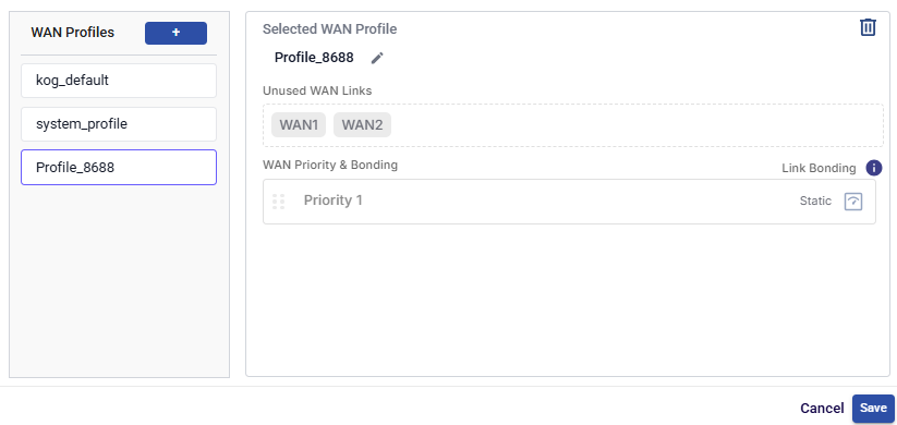
Switch between existing profiles by clicking the name of the WAN Profile from the left menu bar.
-
Click the + button to create a new WAN Profile.
-
Click the

-
Disabled WAN sources are displayed under the section Unused WAN Links.
Note: Only Interfaces enabled on the Interfaces tab will be visible on the WAN Profile screen.
-
Drag and drop the WANs available from the Unused WAN Links section to the respective priority section. More than one WAN (similar or dissimilar type) can be associated with a single priority. In this case, these WANs will be bonded.
-
Link Bonding can be set to Static or Dynamic. By default, the link bonding type is Dynamic, in which case the system distributes the traffic on each WAN link based on performance. In Static Setting, a configured % of traffic is set for each WAN link. For details of the types of link bonding, point to i icon next to the Link Bonding. The user can configure the weighting % of the WAN link.
To configure the weighting %, perform the following steps.
-
Click Static button under the link bonding section.
-
The Weighting % section becomes available.
-
Enter the weighting % for the WAN links. Set equal or varied weightage (e.g., 50–50 for load balancing). User must ensure that the sum of the weighting % for all WAN links must be 100%.
-
Click the Save button to create the WAN Profile.
-
Click the

IP Configuration
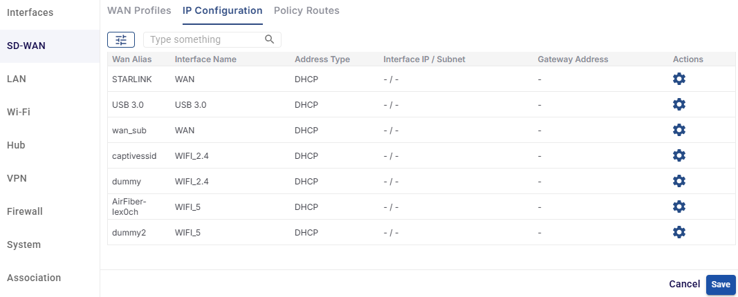
Select the IP Configuration tab in the SD-WAN section. On this tab you can view and manage the IP addressing of each WAN interface on the device. Each WAN can get its address automatically through DHCP or use a static IP address.
-
Click the Refresh button to reload the page with the latest data. The Synced label shows that the configuration has been applied to the device.
-
Only interfaces set up as WAN (including Wi-Fi WAN) in the Interfaces tab are shown on this screen.
The IP Configuration table shows the following information:
-
WAN Alias – The name of the WAN interface, as set in the Interfaces tab (e.g., STARLINK, USB 3.0).
-
Interface Name – The physical or logical port the WAN uses (e.g., WAN, USB 3.0, WIFI_2.4, WIFI_5).
-
Address Type – How the WAN gets its IP address:
-
DHCP – The IP address, subnet and gateway are assigned automatically by the upstream network.
-
Static – The IP address, subnet and gateway are entered manually.
-
-
Interface IP / Subnet – The static IP address and subnet mask of the WAN (e.g., 192.168.10.2/24). DHCP interfaces show "- / -".
-
Gateway Address – The static default gateway of the WAN. DHCP interfaces show "-".
-
Actions – Click the gear icon to edit the IP configuration of the WAN.
-
Use the search field to find a WAN by typing any value from the table. Use the filter icon to filter the list.
Edit IP Configuration
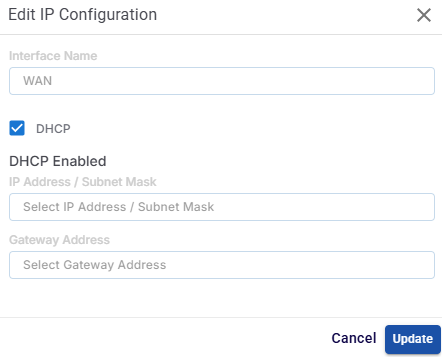
Click the 
-
The Interface Name field shows the interface being edited. It cannot be changed.
-
The DHCP checkbox is selected by default. When it's selected, the dialog shows DHCP Enabled, and the IP address and gateway fields are disabled, because the network assigns these values automatically.
-
To use a static IP address, clear the DHCP checkbox and fill in these fields:
-
In the IP Address / Subnet Mask field, enter the static IP address and subnet mask for the WAN (e.g., 192.168.10.2/24).
-
In the Gateway Address field, enter the default gateway IP address for the WAN (e.g., 192.168.10.1).
-
-
Click the Update button to save the changes for this WAN.
-
Click the Cancel button to discard your changes and close the dialog.
-
Click the Save button at the bottom of the IP Configuration tab to apply all changes to the device.
-
Click the Cancel button at the bottom of the tab to discard any changes that haven't been saved.
Note: Get the static IP address, subnet mask and gateway from your ISP or network administrator. A wrong static configuration can cause that WAN to lose connectivity.
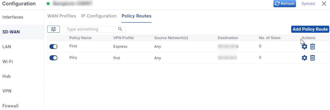
Policy Routes
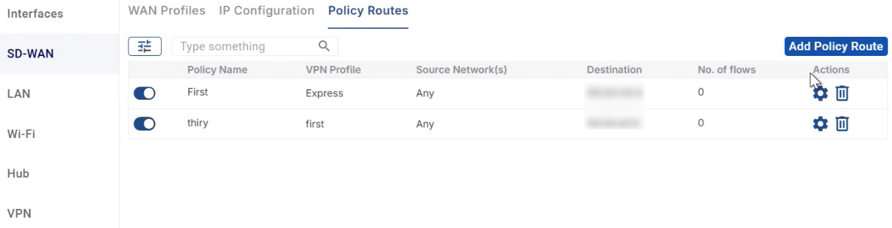
Select the Policy Routes tab in the SD-WAN section. On this tab you can create policy-based routes that send specific traffic through an active VPN profile instead of the normal WAN path. You can pick the traffic by source network, by destination IP and port, or by both.
-
VPN Profile is currently the only supported route type. At least one VPN profile must be active on the VPN tab before you can create a Policy Route.
-
Policy Routes can only be configured from the EpicLink portal. They are not shown on the OpenEdge device's local web interface.
The Policy Routes table shows the following information:
-
Click the Enable/Disable toggle to turn the Policy Route on or off.
-
Policy Name – The name given to the Policy Route.
-
VPN Profile – The VPN profile that the matching traffic is routed through.
-
Source Network(s) – The source IP addresses or subnets whose traffic this route applies to.
-
Destination – The destination IP and port rules this route applies to.
-
No. of flows – The number of traffic flows currently going through the route.
-
Actions
-
Click the
-
Click the

-
-
Use the search field to find a Policy Route by typing any value from the table. Use the filter icon to filter the list.
Add Policy Route
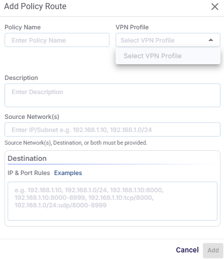
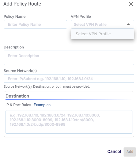
Click the Add Policy Route button to create a new Policy Route. The Add Policy Route dialog box opens.
-
In the Policy Name field, enter a name for the Policy Route.
-
In the VPN Profile field, select the VPN profile to route the traffic through. Only active VPN profiles appear in this dropdown.
-
If no VPN profile is active, the message "No active VPN profiles. Activate one on the VPN tab first." appears below the field. Go to the VPN tab and enable a profile first.
-
-
In the Description field, enter a short description of what the route is for. This field is optional.
-
In the Source Network(s) field, enter the source IP addresses or subnets whose traffic should use the VPN. Separate multiple values with commas (e.g., 192.168.1.10, 192.168.1.0/24).
-
In the Destination → IP & Port Rules field, enter the destination rules for the traffic. Separate multiple rules with commas. Click Examples to see the supported formats:
|
Rule type |
Example |
|---|---|
|
Single IP address |
192.168.1.10 |
|
Subnet |
192.168.1.0/24 |
|
IP address and port |
192.168.1.10:8000 |
|
IP address and port range |
192.168.1.10:8000-8999 |
|
IP address, protocol and port |
192.168.1.10:tcp/8000 |
|
Subnet, protocol and port range |
192.168.1.0/24:udp/8000-8999 |
-
Click the Add button to create the Policy Route. The button becomes active once all required fields are filled in.
-
Click the Cancel button to discard your input and close the dialog.
Note: You must enter Source Network(s), Destination, or both. You can't create a Policy Route with both fields left empty.
Edit / Delete Policy Route
-
Click the
-
Click the
Note: A VPN profile assigned to a Policy Route can't be edited or deleted from the VPN tab. To change or remove that VPN profile, first disable the Policy Route or assign it to a different VPN profile.
LAN
-
Select the LAN option from the side menu bar to open the LAN tab. This tab enables the user to manage VLANs and network address configurations.
-20250811-155249.png?cb=3fff00536b3654d12b72150d457819e7)
-
The user can press on the Refresh button to refresh the page and get the latest data. By default, this screen refreshes every 30 seconds.
The table shows the following information:
-
Network Alias - A name assigned to identify the LAN or VLAN network.
-
VLAN ID - The numeric VLAN tag that separates and identifies the network in a trunked environment.
-
WAN Profile – The WAN routing profile associated with this LAN, determining how outbound traffic is handled.
-
Interface IP / Subnet - Define the IP address and subnet mask (e.g., 192.168.1.1/24).
-
DHCP - Indicates whether the DHCP server is enabled to automatically assign IP addresses to connected clients.
-
Gateway Address - The default IP gateway for devices on this network.
-
DNS Servers - Comma-separated DNS addresses (e.g., 8.8.8.8,1.1.1.1).
-
Actions -
-
Click the
-
Click the
-
Add LAN Network
-
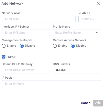
Click the Add LAN Network button to add a new LAN Network with VLAN tagging and optional DHCP configuration.
-
In the Network Alias field, enter a name for the LAN or VLAN network .
-
In the VLAN ID field, tag used to segment network traffic. Allowed Values: 1–4094 (must be unique within the device).
-
Enter the Interface IP/Subnet. This assigns the IP address and subnet mask to this network interface.
-
Select the WAN Profile Name that determines routing and outbound connectivity for the LAN.
-
In the Management Network field, select the Enable radio button to mark this LAN as the management VLAN, used for device configuration access.
-
In the Captive Access Network field, select the Enable radio button to enable a captive portal for network authentication.
-
Select the DHCP checkbox to enable the DHCP server functionality for this LAN. Additional DHCP-related fields become active.
-
Enter the Default DHCP Gateway. This sets the gateway IP assigned to clients. Usually matches the Interface IP.
-
Enter the DNS Servers. This specifies the DNS resolvers provided to clients.
-
Enter the IP Pools. This defines the range of IP addresses the DHCP server can assign to clients.
-
Click the Add button to add the new LAN Network.
-
Fields dynamically enable/disable based on DHCP selection.
-
VLANs must be unique and valid; duplicate detection and validation are performed.
-
Only valid subnet formats are accepted.
-
Management and captive settings trigger icon display in the main LAN view.
Wi-Fi
-
Select the Wi-Fi option from the side menu bar to open the Wi-Fi tab. This tab enables the user to configure Wi-Fi SSIDs and security.
-20250811-201251.png?cb=4c272d5eb7eaf594e46171775a9fa292)
-
The user can press on the Refresh button to refresh the page and get the latest data. By default, this screen refreshes every 30 seconds.
The table shows the Wi-Fi Interfaces List with the following information:
-
SSID – The broadcast name of the wireless network that clients will see and connect to.
-
LAN Name – The LAN or VLAN network that the Wi-Fi interface is mapped to for routing and IP assignment.
-
Wi-Fi Band – The frequency band used for wireless communication (e.g., 2.4GHz for better range, 5GHz for higher speed).
-
Channel – The specific wireless channel in use.
-
Mode – The operational mode of the Wi-Fi interface, typically Access Point for providing network access to clients.
-
Security – The wireless encryption method used, such as WPA2/WPA3 for secured access or Open for no authentication.
-
Actions –
-
Click the
-
Click the
-
Add Wi-Fi Interface
-
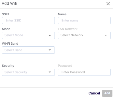
Click the Add Wifi Interface button to add a new Wifi Interface, define its operational mode, assign it to a LAN, and set its security options.
-
In the SSID field, enter a public name of the Wi-Fi network that will be broadcast for client devices to connect to.
-
In the Name field, enter an alias for the Wi-Fi interface, used within the device’s configuration interface.
-
In the Mode field, select the operational role of the Wi-Fi interface from the dropdown menu. Typically Access Point (default) to provide connectivity.
-
In the LAN Network field, select a LAN network from the dropdown menu to associate the Wi-Fi interface with a specific LAN or VLAN. This determines IP addressing and routing for connected clients.
-
In the Wifi Band field, select the frequency range for the network.
-
2.4GHz – Longer range, better wall penetration, but slower speeds.
-
5GHz – Higher speeds, less interference, shorter range.
-
-
In the Security field, select the Security type - WPA2/WPA3 or Open.
-
If the Security is selected as WPA2/WPA3, set a password in the Password field. The password is key that users must enter to join the Wi-Fi network.
-
Open – No password required
-
Note: Use a strong, complex password to prevent unauthorized access.
-
The 'Add' button becomes active once all mandatory fields are filled.
-
Click the Add button to create the interface.
-
Click the Cancel button to discard the input and close the dialog.
-
SSID must be unique within the same band.
-
Mode and band compatibility are validated based on interface capabilities.
-
LAN mapping defines routing and IP assignment behavior for connected devices.
VPN
Workflow Overview
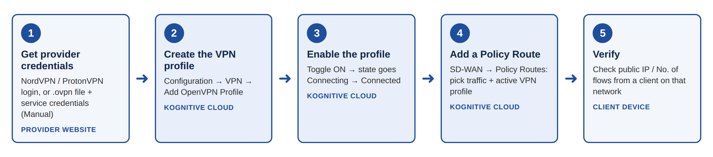
This section walks you through the complete workflow for routing traffic from an Konnect Open device through an OpenVPN tunnel. It covers creating and enabling the VPN profile in EpicLink, and sending the right traffic through it with a Policy Route.
Setting up OpenVPN is a two-part job:
-
VPN profile (VPN tab) – creates the tunnel from the device to a VPN server. On its own, an active profile does not carry any user traffic.
-
Policy Route (SD-WAN → Policy Routes tab) – decides which traffic goes through that tunnel (a LAN subnet, a single host, or specific destination IPs/ports). Traffic that does not match a Policy Route keeps using the device's normal WAN Profile.
Get your VPN provider credentials
Do this on your system, in your VPN provider's website. What details you need depends on the provider:
|
Service Provider in EpicLink |
What you need |
Where to get it |
|---|---|---|
|
NordVPN |
Service credentials (username and password) |
Generated in your NordVPN account dashboard for manual / OpenVPN setup. These are not your NordVPN account login details. |
|
ProtonVPN |
ProtonVPN account username and password |
Your ProtonVPN account login credentials. They must be valid, or the login step fails. |
|
Manual (any other OpenVPN provider, e.g. ExpressVPN, or a private OpenVPN server) |
An .ovpn configuration file for the server/location you want, plus the service credentials that go with it |
The provider's manual / OpenVPN configuration page. The .ovpn file already contains the server and country, so you choose the location when you download the file. |
NordVPN and ProtonVPN are built-in integrations: EpicLink uses their APIs to list countries and servers, so you pick the location inside the portal. Providers without an external API (such as ExpressVPN) are set up with the Manual option and an .ovpn file.
OpenVPN
-
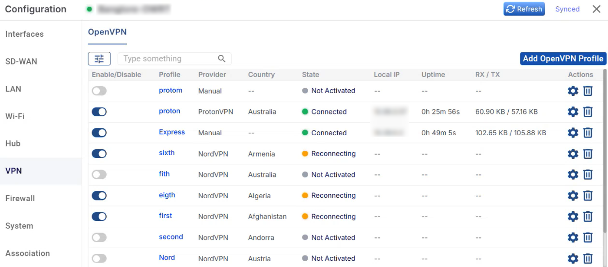
Select the VPN option from the side menu bar to open the VPN tab. On this tab you can create and manage OpenVPN client profiles for the selected device. Once a profile is active, the device sends traffic through a VPN tunnel to a third-party VPN provider or a custom OpenVPN server.
-
Profiles can only be added, edited and deleted from the EpicLink portal.
Note: The VPN profile configurations cannot be performed in the OpenEdge device's local web interface. You can view profile details and enable or disable a profile there, but you cannot create, edit or delete it. The same limit of 8 active profiles also applies on the device.
-
Click the Refresh button to reload the page with the latest data. The Synced label shows that the configuration has been applied to the device.
The OpenVPN sub-tab is selected by default. It shows all OpenVPN profiles configured on the device.
The OpenVPN table shows the following information:
-
Enable/Disable Toggle - Click the toggle to activate or deactivate the VPN profile.
-
Profile - The name given to the VPN profile.
-
Provider - The VPN service provider used by the profile: NordVPN, ProtonVPN or Manual.
-
Country - The country of the VPN server the profile connects to.
-
State - The current connection state of the profile:
-
Not Activated (grey) - The profile is disabled. Every new profile starts in this state.
-
Connecting - The profile has been enabled and the tunnel is being set up.
-
Connected (green) - The VPN tunnel is up and active.
-
Reconnecting (orange) – The profile is enabled, and the device is trying to set up or restore the tunnel.
-
Failed - The tunnel couldn't be set up.
-
-
Local IP - The IP address given to the device on the VPN tunnel. Shown for active profiles only.
-
Uptime - How long the VPN tunnel has been connected. Shown for active profiles only.
-
RX / TX - Data received and sent over the VPN tunnel. Shown for active profiles only.
-
Actions -
-
Click the

-
Click the

-
-
Use the search field to find a profile by typing any value from the table. Use the filter icon to filter the list.
-
Click any Profile name to open its details. The details show the profile's State, Provider, Server, Country and Protocol. For connected profiles, a Live Tunnel section also shows real-time tunnel details: tunnel state, local IP, uptime and RX/TX bytes. This section doesn't appear for profiles that aren't activated. Click the Deactivate button in the details view to disable an active profile.
Note: A maximum of 8 OpenVPN profiles can be active at the same time. When 8 profiles are already active, the Enable toggle for any other profile is blocked and a tooltip shows that the maximum of 8 concurrent VPN sessions has been reached. Disable an active profile first to enable another one.
Add OpenVPN Profile
Click the Add OpenVPN Profile button to create a new VPN profile. The Add OpenVPN Profile dialog box opens.
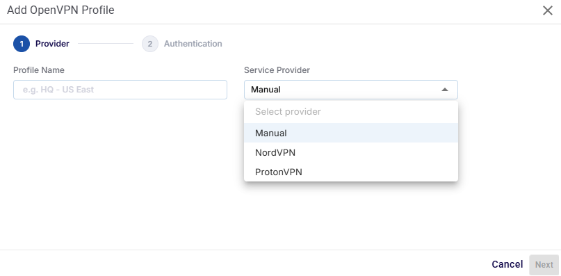
The following Service Providers are supported:
-
NordVPN and ProtonVPN - Built-in integrations. The system uses the provider's API to fetch its countries and servers, so you pick them directly in the dialog.
-
Manual - For any other OpenVPN-compatible provider (for example, ExpressVPN) or a private OpenVPN server. The connection details come from a .ovpn configuration file that you upload.
NordVPN / ProtonVPN
For NordVPN and ProtonVPN, the dialog has four steps: Provider, Authentication, Country and Server.
Step 1 - Provider
-
In the Profile Name field, enter a name for the VPN profile (e.g., HQ - US East).
-
In the Service Provider field, select NordVPN or ProtonVPN from the dropdown menu.
-
Click the Next button.
Step 2 - Authentication
-
In the Username field, enter the username for the selected provider:
-
NordVPN – the service credentials username from your NordVPN dashboard.
-
ProtonVPN – your ProtonVPN account username.
-
-
In the Password field, enter the matching password.
-
Click the Next button. The system checks the credentials with the provider. If they're invalid, an error is shown and you can't move to the next step.
Note: The credentials you need depend on the Service Provider:
-
ProtonVPN – Use your ProtonVPN account login credentials. They must be valid, or you won't be able to log in.
-
NordVPN – Use the service credentials generated in your NordVPN dashboard, not your account login details.
-
Manual – Use the service credentials from your VPN provider that go with the .ovpn file.
Step 3 - Country
-
Once the login succeeds, the system shows the countries available from the selected provider.
-
Select the country you want and click the Next button.
Step 4 - Server
-
The system lists the servers available in the selected country. Each server shows its Server Name, City and Load % (how busy the server currently is; a lower value usually means better performance).
-
Select the server you want.
-
In the Protocol field, select UDP or TCP.
-
Click the Save button to create the profile.
Manual
For the Manual provider, the dialog has two steps: Provider and Authentication. You do not have to pick a country or server, because the .ovpn file already contains that information.
Step 1 - Provider
-
In the Profile Name field, enter a name for the VPN profile.
-
In the Service Provider field, select Manual. This is the default option.
-
Click the Next button.
Step 2 - Authentication
-
Upload the .ovpn configuration file from your VPN provider or server.
-
After the upload, the file name is shown. Click the view option to see what's in the file.
-
In the Username and Password fields, enter the service credentials from your VPN provider that go with the .ovpn file.
-
Click the Save button to create the profile.
-
Click the Cancel button at any step to discard your input and close the dialog.
-
Every new profile starts disabled, with the state Not Activated. Use the Enable/Disable toggle in the OpenVPN table to activate it. The state then changes to Connecting, and then to Connected, or to Failed if the tunnel can't be set up.
Edit OpenVPN Profile
Click the
Note: You can't change the Service Provider of an existing profile. To use a different provider, create a new profile. A VPN profile that is assigned to a Policy Route can't be edited until the Policy Route is disabled or assigned to a different VPN profile.
Delete OpenVPN Profile
Click the
Note: You can't delete a VPN profile that is assigned to a Policy Route (SD-WAN -> Policy Routes). The system shows an error if you try it. First disable the Policy Route or assign it to a different VPN profile, and then delete the VPN profile.
Using VPN Profiles in Policy Routes
The SD-WAN tab of the Configuration dialog box includes a Policy Routes screen, which sends specific traffic through an active VPN profile. When you create a Policy Route, enter a Source Network, a Destination (IP and port rules, comma-separated), or both. At least one of them is required. Only the active VPN profiles appear in the VPN Profile dropdown. Policy Routes can only be configured from the EpicLink portal.
Cellular
-
Select the Cellular option from the side menu bar. This tab provides visibility and control over the device’s cellular modem, SIM cards, carrier details, and SIM failover behavior. It is used to monitor cellular connectivity and configure SIM priority for uninterrupted network access.
-
The Cellular tab is not displayed if the modem is not connected.
-
Cellular features are not available for users with an Essential license.
Instead, the Cellular tab displays a single informational block with the message:
“Upgrade to a Standard license or higher to access Cellular features.” -
Cellular functionality is supported only on Standard and higher license tiers.
Controller
-
The controller tab is selected by default. This section displays real-time cellular modem status, SIM details, and network information.
-20260122-070922.png?cb=fd409c549819f7be107eb288cfb89b8e)
-
Active Label - This indicates the SIM currently used for cellular connectivity.
-
Refresh - Fetches the latest cellular and SIM status from the device.
-
Synced - Confirms that the SIM configuration is successfully applied to the device.
Device & Modem Information
-
Connection Status - Connected / Disconnected indicator shows the current cellular connectivity state. A green Connected status confirms the device is actively connected to a cellular network. The explanations for all supported states are as follows:
-
Not Available – Modem not on bus / resetting / failed
-
No SIM / Idle – No SIM present, cannot register
-
Searching – Searching for network
-
Registered – Registered and may connect
-
Connecting – Connecting to network
-
Verifying – Verifying data path
-
Connected – Successfully connected
-
Registration Denied – SIM denied by the network
-
Error – Modem error
-
Switching – SIM switching in progress
-
-
Click the Reset Modem

-
Click the Reload SIM

Note: Reload SIM has to be performed whenever any physical changes to the SIMs are done, like adding/removing/swapping SIM on the system.
-
Device Model - Displays the cellular modem hardware model (e.g., Epic WaveLink 5G).
-
IMEI - The unique identifier of the cellular modem. Used for carrier registration and troubleshooting.
-
Firmware - Shows the currently installed modem firmware version.
-
Serial / DID - Unique serial number or Device Identification Number of the device.
SIM Slot Information
-
SIM A / SIM B Panels - Shows the physical SIM slots available on the device.
-
Displays the current SIM status:
-
Active – SIM currently in use.
-
No SIM Detected – No SIM inserted or recognized.
-
Standby - SIM is available but it is not currently in use.
-
-
-
ICCID - This is a unique identifier of the SIM card. It is useful for carrier validation and inventory tracking.
-
APN (Access Point Name) - The APN used to establish data connectivity with the carrier.
-
Carrier Name - Displays the mobile network operator (e.g., T-Mobile).
SIM Settings
-
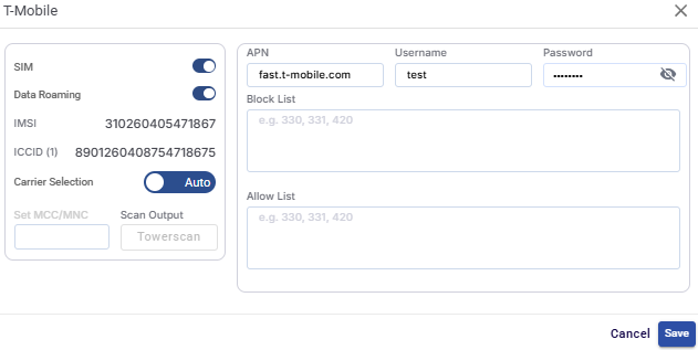
Click the SIM Settings icon

-
SIM Toggle button - Enables or disables the selected SIM card.
-
Data Roaming Toggle button - Controls whether the SIM is allowed to connect to roaming networks.
-
Enabled SIM can connect to partner networks outside the home carrier.
-
Disabled SIM can connect to the home network only.
-
-
IMSI - Shows the International Mobile Subscriber Identity associated with the SIM.
-
ICCID - Shows the Integrated Circuit Card Identifier, a unique identifier for the SIM card.
-
Carrier Selection - Defines how the cellular network operator is selected.
-
Auto:
-
The modem automatically selects the best available carrier.
-
Recommended for most deployments.
-
-
Manual:
-
Allows manual selection of a specific carrier (if supported).
-
Manually specifies the Mobile Country Code (MCC) and Mobile Network Code (MNC).
-
Scan Output (Towerscan) - Scans and lists available cellular towers and networks.
-
-
-
Enter the APN used to connect to the carrier’s data network.
-
Enter the Username required for APN authentication.
-
Enter the Password associated with the APN username.
Note: Username and Password are optional fields and might not be applicable for all networks.
-
Enter the Block List details. This prevents the SIM from connecting to specific carrier networks. Enter comma-separated MCC/MNC values.
-
Enter the Allow List details. This restricts connectivity to only specified carrier networks. Enter comma-separated MCC/MNC values. If an Allow List is configured, the SIM will connect only to the listed networks.
-
Click Save button to apply the SIM configuration changes.
-
Click Cancel button to discard all changes and closes the SIM Settings screen.button to apply the SIM configuration changes.
-
Click Cancel button to discard all changes.
Network & Signal Information
-
Network Type - Shows the cellular technology in use (e.g., 5G SA).
-
Signal Strength - Visual indicator showing signal quality.
-
SNR (Signal-to-Noise Ratio) - Indicates signal clarity.
-
An SNR value above 12.5 dB indicates excellent signal quality.
-
An SNR value between 10 - 12.5 indicates good signal quality.
-
An SNR value between 7-10 indicates fair signal quality.
-
An SNR value below 7 indicates poor signal quality. These details are shown by the below color codes.
-
If Roaming is enabled on any of the SIM, it is denoted by the R icon.
-
-20260123-133605.png?cb=1fbd18ec081bf53654e3e877591cb949)
-
Band - Cellular frequency band currently used by the modem.
-
Bandwidth - Channel bandwidth allocated by the carrier.
-
MCC / MNC - Mobile Country Code / Mobile Network Code identifying the carrier network.
-
Cell ID - Identifier of the connected cellular tower.
-
PLMN - Public Land Mobile Network code of the serving network.
-
TX / RX Data Usage - Shows transmitted and received data volume over the cellular link.
SIM Priority
-
Click the SIM Priority tab. This section controls how the device selects and switches between available SIM cards.
-20260122-072602.png?cb=4854f6ff8cca5ba83351d73173da8b2e)
-
The table shows the following information:
-
SIM Slot - Indicates whether the SIM is in slot A or B.
-
Carrier - Mobile operator associated with the SIM.
-
IMSI - International Mobile Subscriber Identity.
-
ICCID - Unique SIM card identifier.
-
APN - Access Point Name configured for the SIM.
-
Carrier Selection - Indicates whether carrier selection is Auto or Manual.
-
Roaming - Shows whether roaming is enabled or disabled for the SIM.
-
SIM Priority Mode
-
Auto Mode (Default)
-
All SIMs are treated equally.
-
The device stays on the current SIM as long as connectivity is stable.
-
Automatically switches to another available SIM if signal is lost.
-
-
Manual Mode
-
Allows administrators to manually define SIM priority. Drag and drop on the table to set the SIM priority.
-
Useful when one SIM should always be preferred over others.
-
The device will stay on the selected SIM even if it becomes unreachable. It will not switch to another SIM automatically.
-
Click the Save button to apply SIM priority configuration changes.
-
Click the Cancel button to discard the changes.
-
System
-
Select the System option from the side menu bar to open the System tab. This tab enables the user to perform system-level actions like update software, reboot device, and configuration management.
-20250812-070825.png?cb=c63ba58d5b578b2a6cbb7d81f0657894)
-
The user can press on the Refresh button to refresh the page and get the latest data. By default, this screen refreshes every 30 seconds.
-
The Device Name field shows the name of the device in the network.
-
The System Uptime field shows how long the device has been running since the last reboot.
-
The Konnect Status field indicates whether the device is online and connected. The below color convention describes the status of the device.
-
Green Dot: Connected.
-
Red Dot: Disconnected.
-
-
The Device Model field displays the model number of the hardware.
-
The Latest Available Software field shows the most recent firmware/software version available for the device.
-
The Current Software Version field displays the software version currently installed on the device.
-
Click the Reboot Device button to restart the device.
-
Click the Update Software button to update the device to the latest available software version.
Configuration
-
The Software Version field shows the version of the system configuration.
-
The Configuration Creation Date field shows the date when the current configuration file was created.
-
In the File Name field, enter a name when saving the current device configuration.
-
Click the Save Configuration button to save the current system configuration for backup purposes.
-
In the Upload Device Configuration field, select the type of configuration to upload to the device from the dropdown menu. The options available are Startup, Running, Backup.
-
Click the Upload Configuration button to upload the selected configuration file to the device and apply it.
Association
-
Select the Association option from the side menu bar to open the Association tab. This tab shows the device’s current organizational association and licensing details. It also provides controls for moving the device between organizations or to warehouse or changing its license.
-20250812-073252.png?cb=2697ab0a6c85ab2a1abacaf6111a528c)
-
The user can press on the Refresh button to refresh the page and get the latest data. By default, this screen refreshes every 30 seconds.
Current Device Association
-
Under the Current Device Association Section, the Device Hierarchical Path section shows the full organizational structure where the device is currently associated.
-
The format is Organization / Site / Device Name. This helps to identify the exact location of the device in large multi-site deployments.
-
-
Click the Move Device button to transfer the device to another organization or site within the management system. The Move Device dialog box opens.
Move Device Only
-
Select the Move Device Only (Keep Existing Site) radio button to move the device to another Organization or Site.
-20250812-074646.png?cb=141045d728b3236867283225ed2c4930)
-
Select the required organization from the dropdown menu in the Organization field.
-
Select the required site from the dropdown menu in the Site field.
-
The Device field shows the name of the selected device.
-
Select the Move Device button to move the device to the selected organization and site.
Move Site and All Devices
-
Select the Move Site and All Devices radio button to move an entire and all its devices to another organization.
-20250812-075518.png?cb=620d416aea9140a49fc717620f3f218a)
-
Select the required organization from the dropdown menu in the Organization field.
-
The Site field shows the name of the selected site.
-
The Device field shows that all devices will be moved.
-
Select the Move Site button to move the site to the selected organization.
Move Device to Warehouse
-
Select the Move Device to Warehouse radio button to move the device back to the warehouse.
-20250812-081850.png?cb=1ea6f30560d836bd994440adbed52887)
-
The Organization field shows the name of the selected organization.
-
The Site field shows the name of the selected site.
-
The Device field shows the name of the selected Device.
-
Select the Move To Warehouse button to move the device to the warehouse.
License
-
The License field shows the type of license currently assigned to the device.
-
The Term field shows the full duration of the license.
-
The Term Ends field shows the expiry date of the license. The user can monitor this field to avoid service interruptions and plan renewals.
-
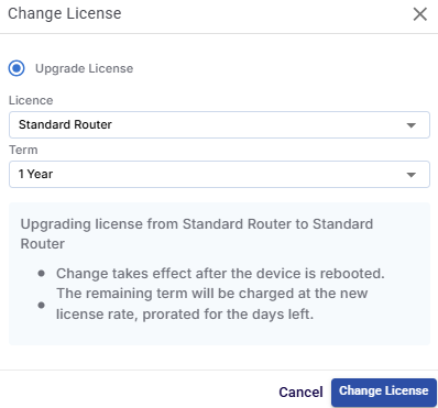
Click the Change button to modify the license type or duration for the device. The Change License dialog box opens.
-
In the License field, select the required license type from the dropdown menu.
-
In the Term field, select the required license term from the dropdown menu.
-
Click the Change License button to update the license details and save the changes.
Hub Dropoff
The Hub Dropoff feature allows supported WAN interfaces to route internet traffic through a managed cloud tunnel server (Hub POP). This enables centralized traffic routing, cloud-managed internet breakout, and bandwidth usage monitoring.
The feature is available only for devices assigned with supported licenses listed below:
-
Standard Router
-
Standard Router Captive
Standard Router + Hub
-
Standard Router + Hub (500GB)
-
Standard Router + Hub (2TB)
-
Standard Router + Hub (metered)
Standard Router Captive + Hub
-
Standard Router Captive + Hub (500GB)
-
Standard Router Captive + Hub (2TB)
-
Standard Router Captive + Hub (metered)
Under the License section, click the Change button to change the license type of the device. The Change License dialog box opens.
-
In the License field, select a Hub License from the dropdown menu based on your required data usage quota.
-
Click the Change License button.
-
Once a Hub-supported license is assigned, the Hub tab becomes available in the side menu bar of the Configuration dialog box.
Hub - Configuration
-
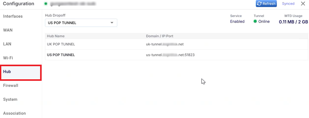
Select the newly available Hub option from the side menu bar.
-
This screen shows the Available Hub servers, Tunnel status, Service status and Usage information.
-
Open the Hub Dropoff dropdown and select the required Hub server. For example: US POP TUNNEL, UK POP TUNNEL.
-
The selected Hub server becomes the active cloud tunnel endpoint.
-
The Service field shows whether Hub service is enabled.
-
The Tunnel field shows the tunnel connection status.
-
The MTD Usage field shows the Month-to-date bandwidth usage.
-
When the quota limit is reached:
-
Hub service is automatically disabled
-
Traffic no longer routes through the Hub tunnel
-
-
-
The Domain / IP:Port column shows the Hub tunnel endpoint.
Interfaces - Configuration - Enabling Hub Dropoff on Interfaces
-
Enabling the Hub Dropoff feature in the Interfaces screen decides:
-
which WANs participate in the hub tunnel
-
which WANs bypass it
-
-
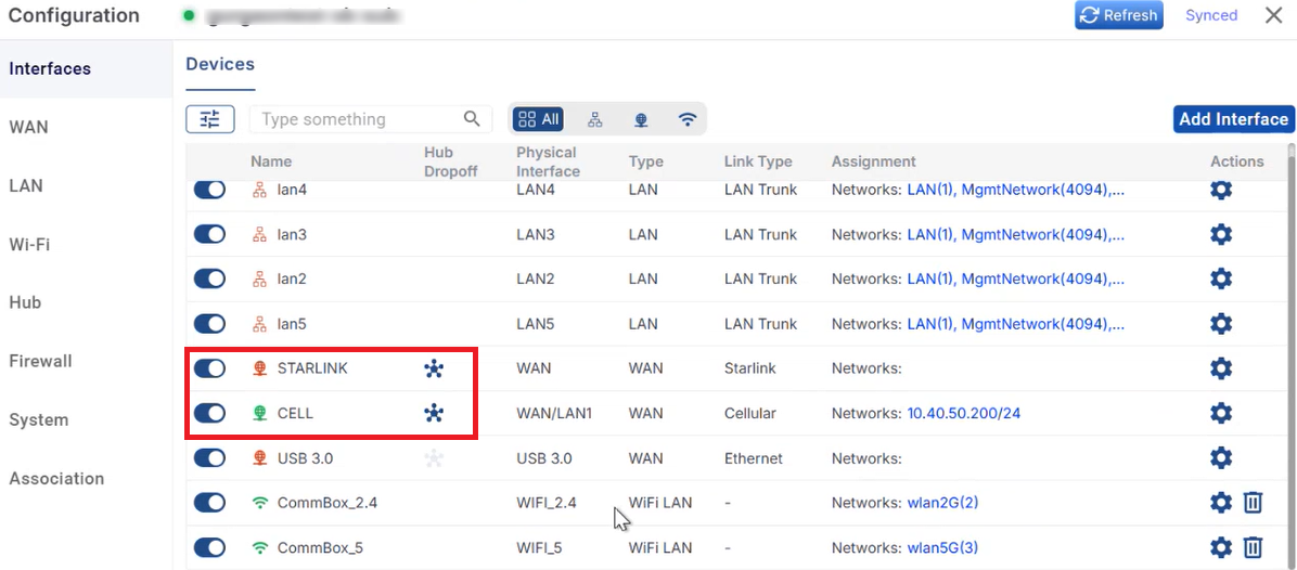
Select the Interfaces option from the side menu bar.
-
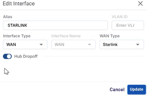
Choose the required WAN interfaces and select the Gear

-
Enable the Hub Dropoff toggle button.
-
Click the Update button to save the changes.
-
The supported interface types are:
-
WAN
-
Wi-Fi WAN
-
-
In the Interfaces table, these interfaces display a Hub icon

-
Bright Hub Icon - Hub Dropoff enabled
-
Faded Hub Icon - Supported but disabled
-
No Hub Icon - Hub Dropoff unsupported
-
-
Click the Hub icon
Conclusion
The Configuration dialog box centralizes all essential settings in one clean, manageable UI. Whether editing interfaces, assigning priorities, pushing system updates, or managing licenses, this screen ensures efficient administration of connected devices. Designed with scalability in mind, it empowers users to configure and control large fleets of network devices effortlessly.