
-
Select the Routes option from the left menu bar.
-
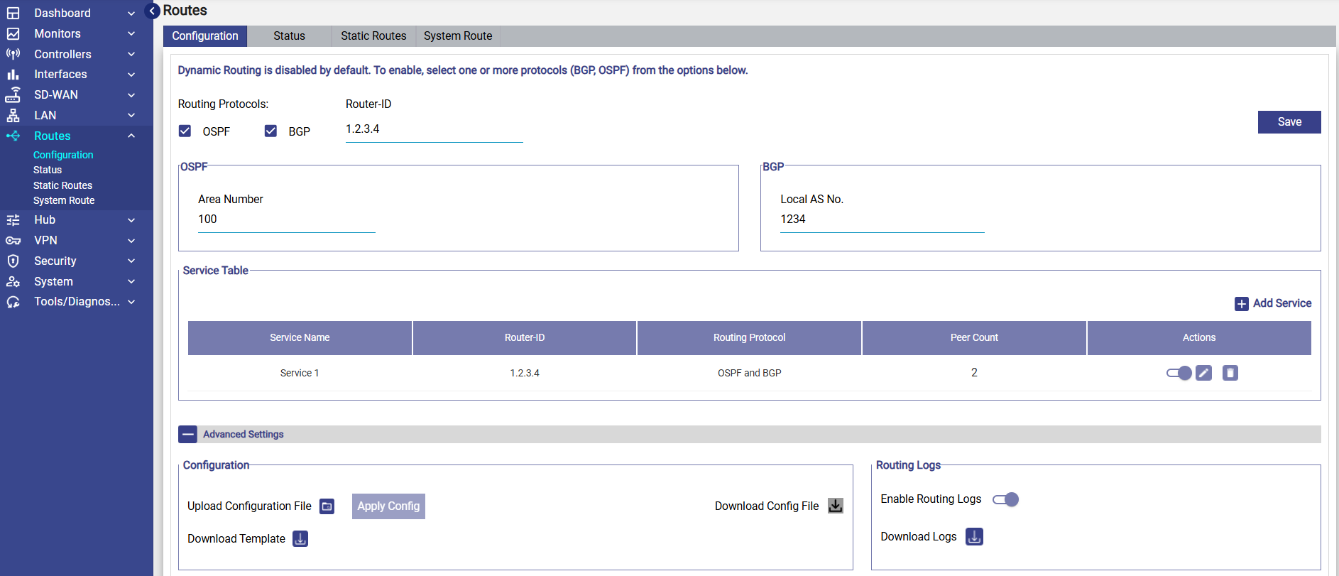
The Configuration tab will be selected by default.
-
At the top of the Configuration screen, the user will see the following checkboxes:
-
OSPF
-
BGP
The user can enable either or both protocols depending on the network design. These protocols define how routing information is exchanged with neighboring routers.
-
-
Enter the Router ID. This is an unique identifier for the router and is used by both OSPF and BGP. Enter it in IPv4 format (e.g., 1.2.3.4). This value must be unique within the routing domain
OSPF Settings
When OSPF is enabled, the following setting appears:
Area Number
-
Specifies the OSPF area where this router operates.
-
Default and most common value: 0 or 100 (depending on network design).
-
All routers in the same OSPF area share routing information.
BGP Settings
When BGP is enabled, the following setting appears:
Local AS Number
-
Autonomous System (AS) number assigned to this router.
-
Can be a private AS (e.g., 65001–65535) or public AS based on the network design.
Service Table
Dynamic Routing configuration is organized using services, similar to the Carrier Hub routing model.
The service table shows the Dynamic Routing Services created. It shows the following information:
-
Service Name
-
Router-ID
-
Routing Protocol
-
Peer Count
-
Actions (Enable/Disable, Edit, Delete)
Each service contains:
-
Participating WAN interfaces
-
Neighbor routers (peers)
-
Routes that are advertised externally
Add a new Service
-
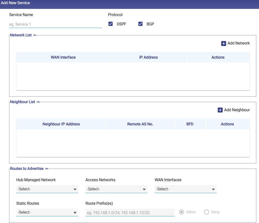
Click the Add Service button to create a new Dynamic Routing service. This opens the Add New Service window.
-
Enter the Service Name.
-
Protocol Selection - Tick one or both: OSPF / BGP.
-
This defines which protocols the service will operate on. Protocol selection determines which configuration fields are displayed.
-
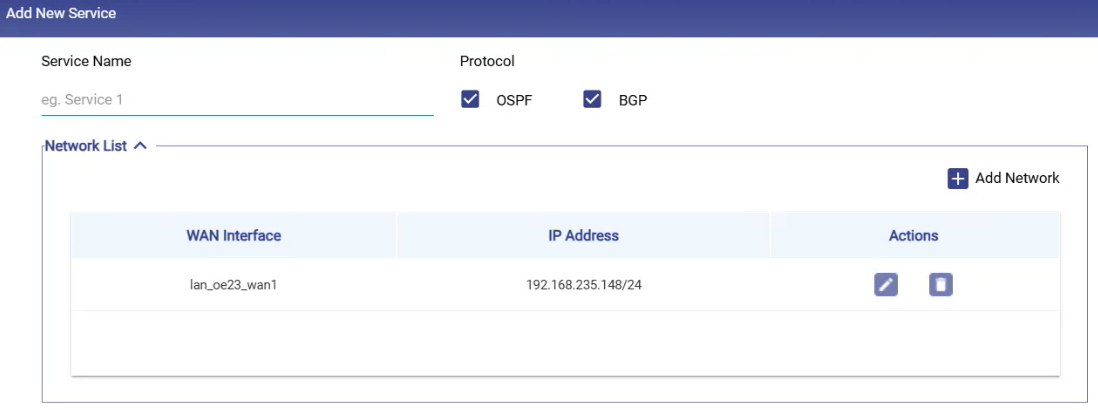
Network List
-
This section lists the interfaces that will participate in dynamic routing.
-
It shows the following information:
-
WAN Interface
-
IP Address
-
Actions (Edit/Delete)
-
-
Select the Add Network button to add a new network.
-
Select the WAN Interface.
-
Enter the IP address with subnet.
-
Select the

-
These interfaces become the endpoints used to communicate with OSPF neighbors or BGP peers.
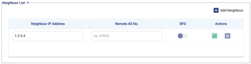
Neighbour List
-
This section defines neighboring routers with which routing information will be exchanged.
-
It shows the following information:
-
Neighbour IP Address – Remote router’s IP.
-
Remote AS Number (BGP only) – The AS number of the peer router.
-
BFD (Bidirectional Forwarding Detection) – Optional fast-failure detection.
-
-
Select the Add Neighbour button to add a neighbour.
-
Enter the Neighbour IP Address.
-
Enter the Remote AS Number.
-
Select the
-
Neighbour configuration follows the same behavior and validation model used in Carrier Hub routing.
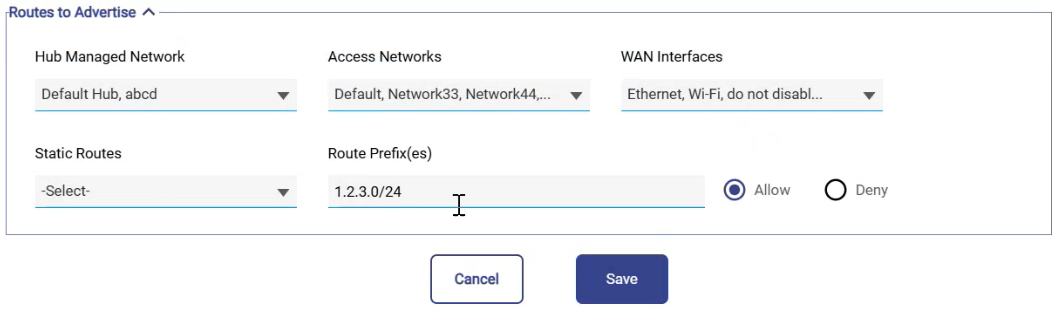
Routes to Advertise
-
The Routes to Advertise section defines which internal networks will be advertised to upstream routers.
-
In the Hub Managed Network field, select from available hub networks to advertise.
-
In the Access Networks field, select which local Access Networks will be announced.
-
In the WAN Interfaces field, specify through which WAN interfaces these routes should be advertised.
-
In the Static Routes field, choose which ones to advertise if you have existing static routes.
-
In the Route Prefix(es) field, manually enter one or more prefixes (e.g.,
1.2.3.0/24).-
Choose whether to allow or block advertisement of the selected prefixes.
-
-
Click the Save button to save the changes.
-
The service will now appear in the Service Table. The user can Enable/Disable it anytime using the toggle button in the Actions column.
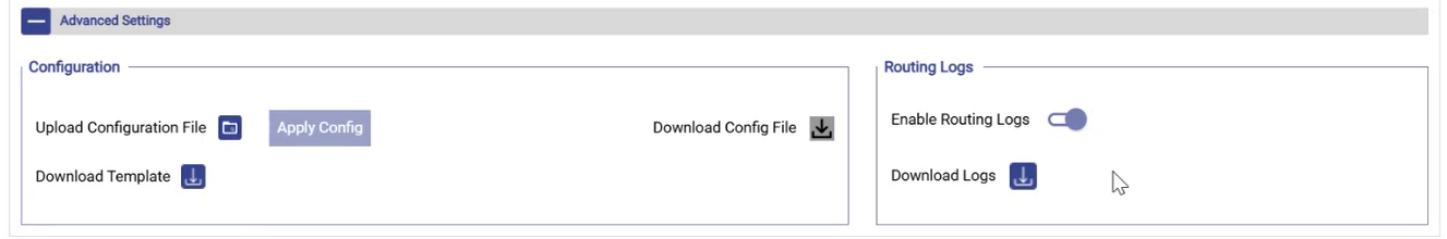
Advanced Settings
At the bottom of the configuration page, the user can find the Advanced Settings section.
-
The user can also upload the dynamic routing configuration in CSV format.
-
Under the Configuration section, click the Download Template button to download the sample file.
-
Enter the details of the dynamic routing config in the sample file and save the file.
-
Click the

-
Select the Apply Config button to apply the dynamic routing configuration from the file.
-
Select the Download Config File icon to exports the currently active dynamic routing configuration.
Note: NAT must be disabled on involved interfaces for proper dynamic routing.